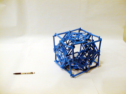
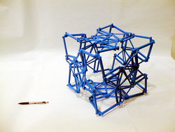
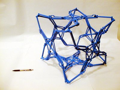
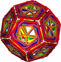
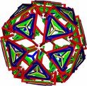
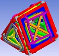
Since deployable mechanisms do not all function in the same manner, each mechanism has its own advantages and disadvantages. Several deployable mechanisms have been developed in the laboratory, their main characteristics being the following:
- the mechanisms have only 1 DOF;
- the mechanisms always keep the same gemometric shape;
- the mechanisms always have an empty centre;
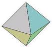
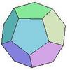
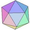
- the mechanisms are based on the five Platonic solids.
The design was achieved in paying special attention to mechanical interferences, which were eliminated, and to the optimization of the mechanism as a function of its expansion ratio.
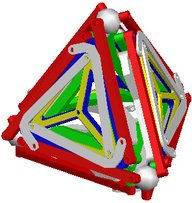
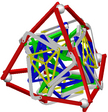
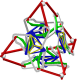
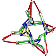
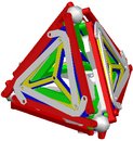
An example of a tetrahedron deployable mechanism is given below. As shown, the centre of the mechanism is always empty, no matter what position of elongation the mechanism takes on. Moreover, the geometric shape of each of its faces, which are triangles in this case, is always maintained, if for example the face is clearly illustrated by connecting a cloth to the three vertices. In addition, the mechanism requires only one single motor to allow it to expand or contract. Only a single mobile polygon located on each face has to be actuated. The other faces automatically follow the movement as a result of the architecture of the system.
Poster
A poster on deployable mechanisms was prepared in 2002 and can be downloaded here 1 DOF Deployable Mechanisms
Selected photos
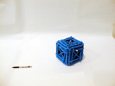
Several photos of deployable mechanisms are provided below. The images can be enlarged by clicking directly on the photos.

